

Energizing the Next Generation
Decarbonization is becoming the most important driver of change in mobility. To achieve the targets set, individual mobility must be placed on an ecologically sustainable footing. Above all, this requires sustainable concepts and innovative mobility solutions.
What role do electric and renewable energy sources play in this? What contribution do intelligent, networked and self-driving mobility solutions based on modular platforms make?
We presented our answers to you at the Schaeffler Kolloquium, the most important customer event of the Automotive Technologies Division at Schaeffler.
See some of the showcased highlights here:


Thank you for joint exchanging ideas
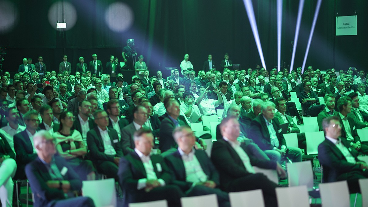
It was a great pleasure to welcome numerous guests to this year's Schaeffler Kolloquium in Bühl. Many thanks to all those present for taking the time to exchange ideas together and for their interest in our latest technologies, concepts, and solutions for sustainable mobility.
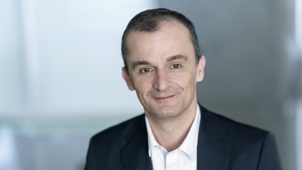
Matthias Zink
CEO Automotive Technologies
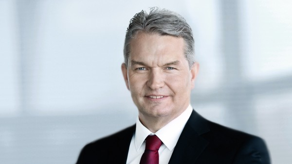
Wendelin Backes
Head of Global Key Account Management
The Kolloquium awaited you with exciting topics
Highlights
The Schaeffler Kolloquium stands for innovation, full customer focus and joint exchange. In an exclusive setting, we not only presented our latest intelligent components, systems and services, but also allowed you to actively experience them.
Digital conference book
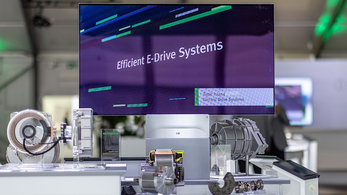
Powertrains of the future – efficient and electric
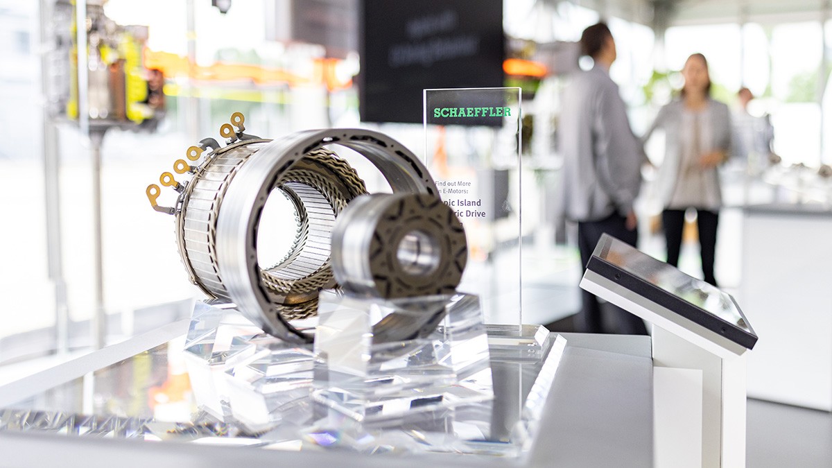
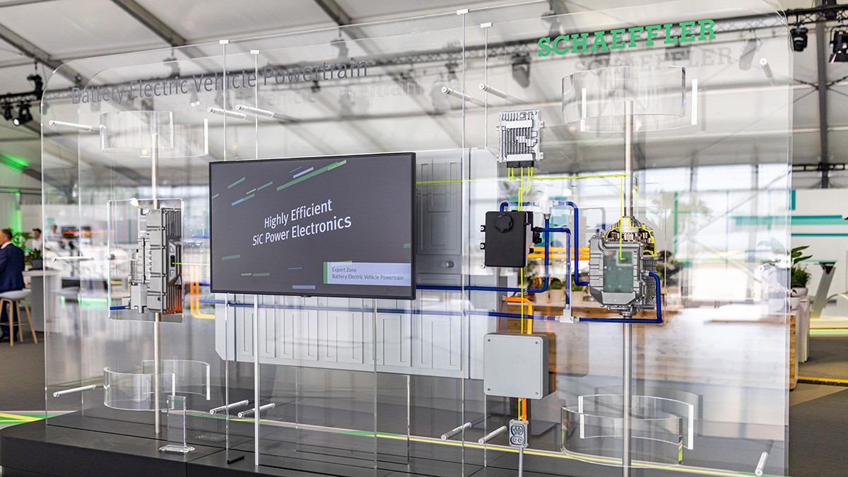
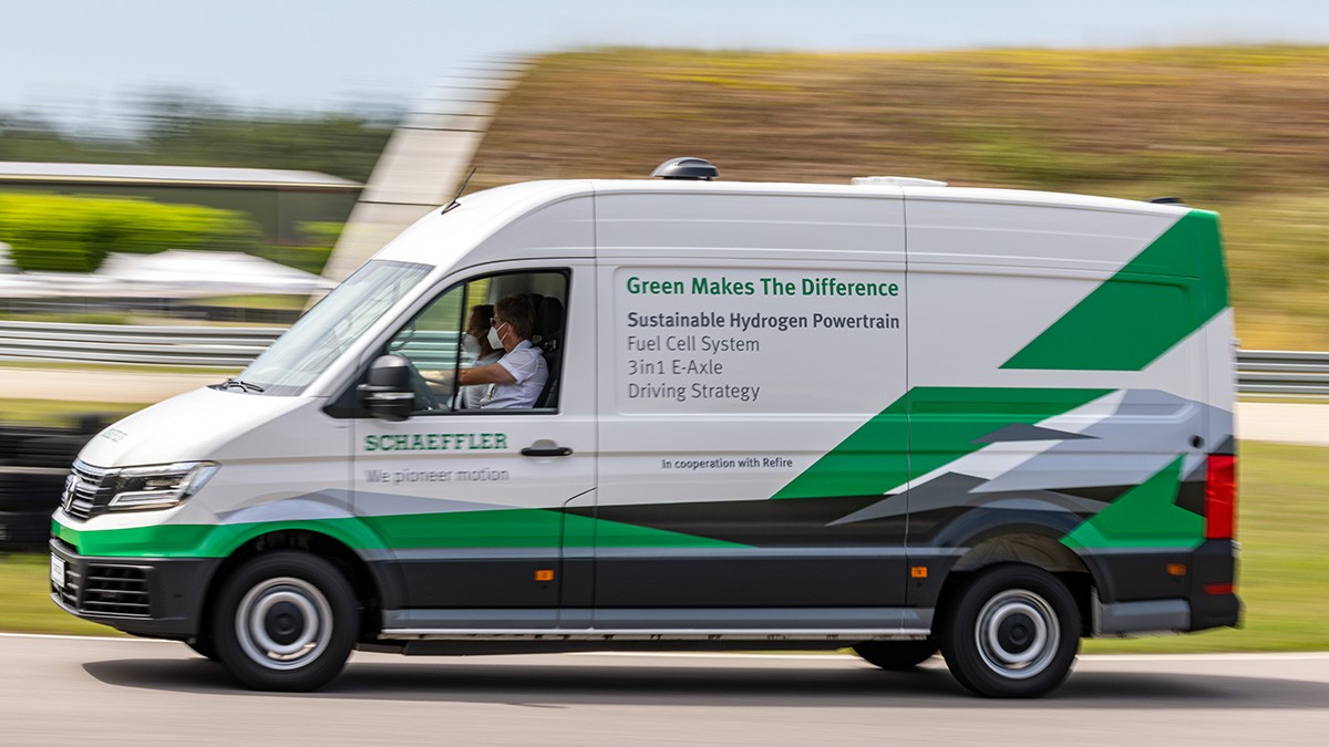
Only with a consistently well thought-out electrification of the powertrain will it be possible to fully achieve the decarbonization targets. Whether purely electric, hybrid or hydrogen technology – the powertrain of the future must be innovative, efficient and powerful. We will present our complete portfolio of the latest customized solutions for the electrified powertrain.
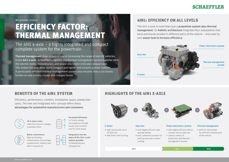
Experience the Schaeffler 4in1 e-axle live: It combines the components motor, gearbox, power electronics and thermal management into an innovative overall system. The high level of integration of the components, in combination with intelligent control and a highly engineered architecture, enables the optimum use of existing thermal energy. The system thus stands for both an increase in electric range and an increase in comfort.
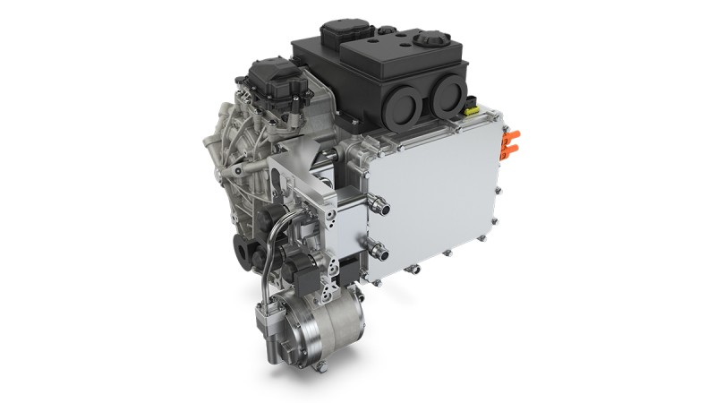
The 4in1 e-axle comes with an integrated cooling and refrigerant system for air conditioning the interior and the entire powertrain.
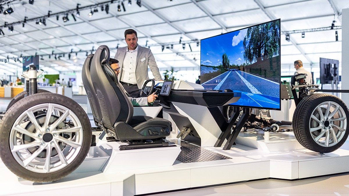
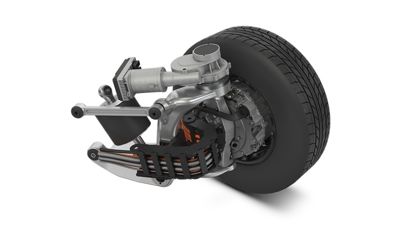
Innovative Chassis Systems – intelligent, safe and consistently available
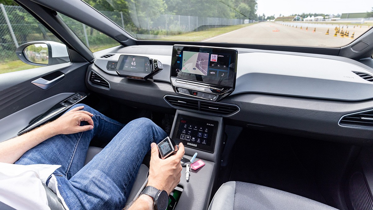
Vehicles with automated driving functionalities must be absolutely reliable and safe. This places the highest demands on chassis components in terms of intelligence, safety and availability. With the Chassis Demonstrator, we show you how intelligent chassis systems and innovative steering solutions of the future will affect the driving experience. Take a seat and steer with Space Drive "by-wire", i.e. without any mechanical connection between steering wheel and axle – the steering signals are transmitted electronically. Constant availability is the top priority; safeguarded by Space Drive's multiple redundancy.
The intelligent Rear Wheel Steering System (iRWS) optimizes maneuverability and reduces a vehicle's turning circle – a great relief, especially in inner-city traffic! At higher speeds, the focus is on safety: thanks to steering in the same direction on the front and rear axles, controlled and agile lane changes become a reality – with maximum driving comfort for the passengers.
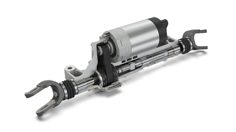
Thanks to intelligent Rear Wheel Steering (iRWS), the turning circle of a vehicle is significantly reduced.
New mobility solutions – driverless towards the future
Agile, autonomous, connected and electric – these are the requirements for mobility solutions for the city of the future. Our innovative Rolling Chassis – a scalable platform for new, driverless mobility solutions – makes this happen. Universally applicable, it offers entirely new forms of autonomous mobility: from passenger and logistics to service applications such as cleaning machines. The platform, designed for a wide variety of vehicle classes, demonstrates the wide range of Schaeffler technologies: different combinations of drive and steering systems can meet a wide variety of customer requirements in terms of maneuverability and performance.
Equipped with four iCorner Modules and Intelligent Vehicle Dynamics Control, the Rolling Chassis impresses with a steering angle of up to 90 ° and thus maximum maneuverability. Steering, driving, braking and wheel suspension in the smallest possible installation space thus enabling entirely new vehicle architectures.
With a steering angle of up to 90 °, the iCorner Modules guarantee maximum maneuverability.
Lectures
Exclusive expert presentations provided exciting insights into our latest innovations in terms of sustainable concepts and innovative mobility solutions.
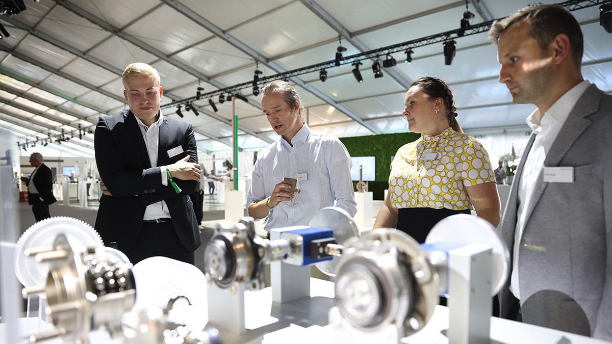
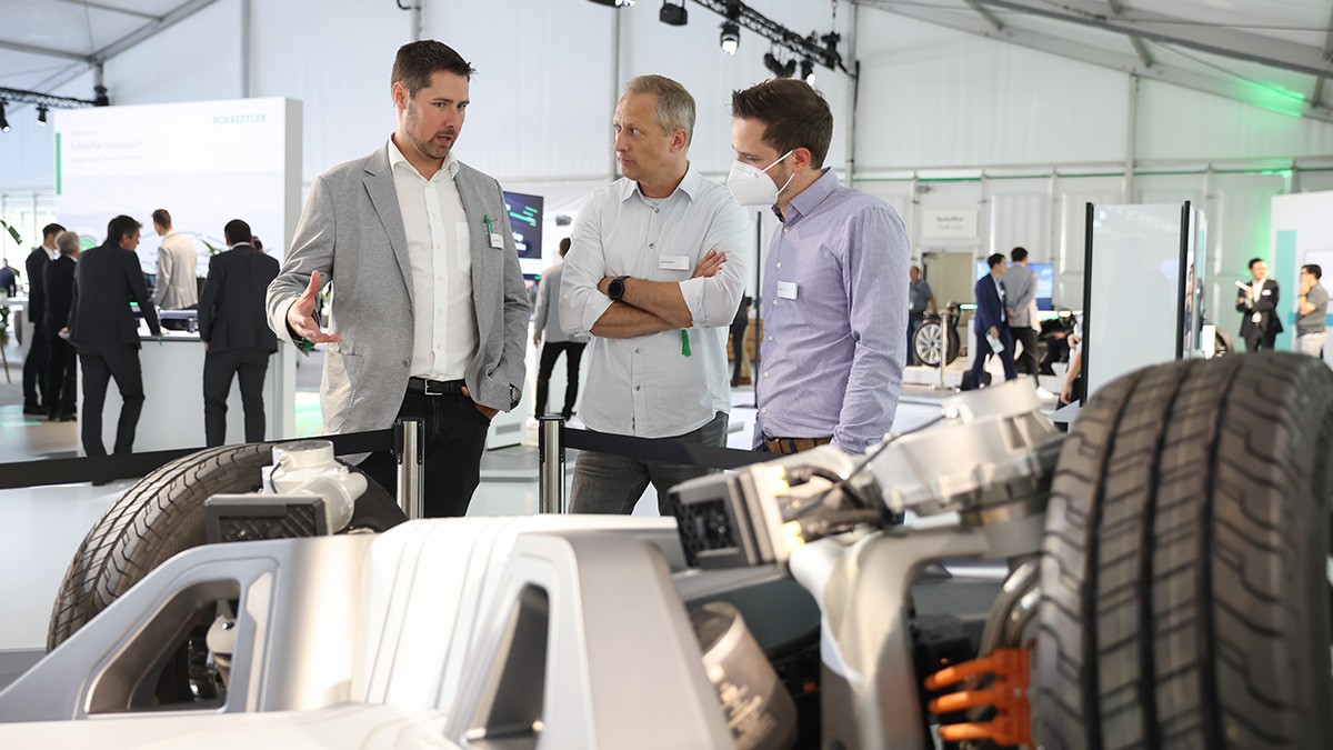
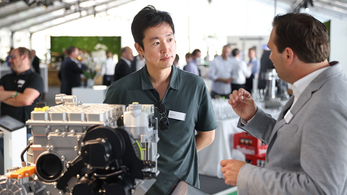
Exhibition
In the adjoining technical exhibition, we presented our latest developments in the areas of chassis and powertrain technology. The guests could see for themselves our latest intelligent components, systems and services, and at the same time took the opportunity to exchange experiences together.
Driving Experience
During a personal test drive guests were able to see first-hand how powerful our latest developments are in terms of fully integrated and connected chassis solutions as well as efficient solutions for powertrain electrification and hybridization. On the test tracks of the Driving Center Baden, various concept vehicles were available for a test drive with our instructors.
Plant tour
We showed how the profound transformation of the automotive industry is also leaving its mark on manufacturing by providing a tour through our plant! It became clear how we have impressively expanded our production competence in the area of e-mobility, building on mechanical manufacturing excellence. The plant tour showed, among other things, at stations such as the clean room for actuator production or the small series for traction e-motors, how we have positioned ourselves to master the challenges of the future.
A focus on sustainability

Sustainability forms an integral part of Schaeffler's corporate strategy. We also always kept sustainability in mind in our event management.
For the organization of the Kolloquium, our sustainable approach at Schaeffler meant that we questioned many circumstances and considered all facets of the event. Our goal was to make the Kolloquium 2022 noticeably more climate-friendly.
This included, for example, our additional group shuttles, the saving of resources, and the regional and seasonal catering menus. In addition, after the event we evaluated and compensated all emissions that could not be prevented or reduced completely.
Find out more about our sustainability targets at Schaeffler.
Media contact & downloads
For media inquiries about the Schaeffler Kolloquium, please contact:
In our digital conference book, brochures and publications, you will find more information about the contribution Schaeffler is making to sustainable mobility and motion of the future.